This is part 2 of the R2D2 animatronic project. In the last post I went over the hardware I’m using and some of the very basic stuff at the beginning. Here, I’ll go into some more detail on the code and hardware being used to make the head rotate and the LED flash, which – so far – looks a bit like this:
So, I think that’s not to shabby myself. Basically, the head is setup so that it rotates randomly, up to 1/3rd of a rotation in each direction from a centre point. The LED flashes randomly, independently of the head rotating. That turned out to be harder than I expected, but I’ll get into that shortly.
As I said last time, this project is using a stepper motor from my old Ender 5 Pro 3D printer. I think a stepper isn’t the ideal motor to use here, but it’s what I’ve got. So, using a little bit of example code from the stepper library and some googling, I managed to come up with something that… didn’t really work. At all. This threw me for a bit.
See, I’d never done any work with any Arduino-type devices, and I’d never programmed in C++ before. I’ve got some experience in other languages, so I’m not a total novice, but I’m far from an expert as well. After some more googling, I found an example script that actually didn’t use the stepper library at all, but totally worked. So I took that as the base, and put together a simple script that would randomly rotate the head left and right.
I added in some logic to track how many steps the motor had taken so that I could make sure it didn’t rotate too far – i.e. rotating all the way round so he’s facing the back. I think this could be the advantage of using the stepper though, it’s easy to know how far you’ve moved, because you do it in definite steps.
The wiring for this part looks a little like this:
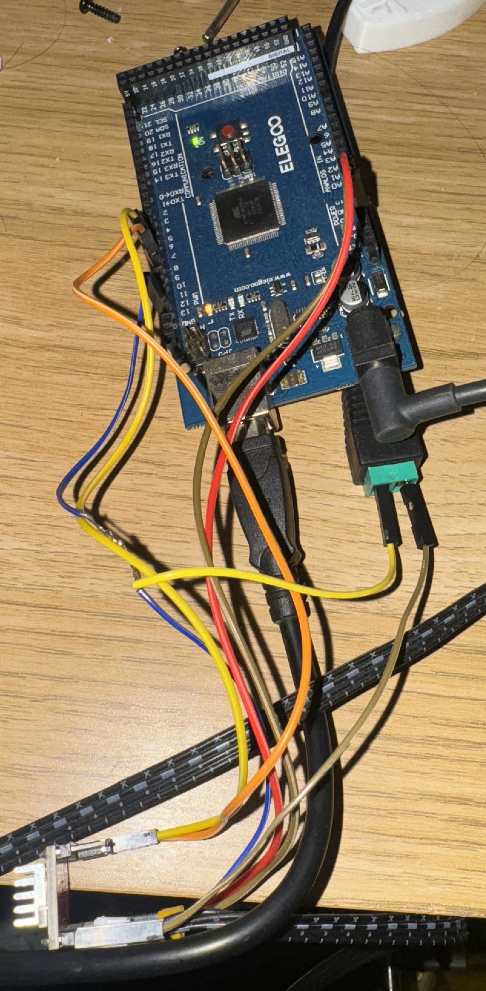
Now that’s a bit of a mess, so I’ll pop this diagram in here as well to make it a bit clearer, and I’ll talk through it here
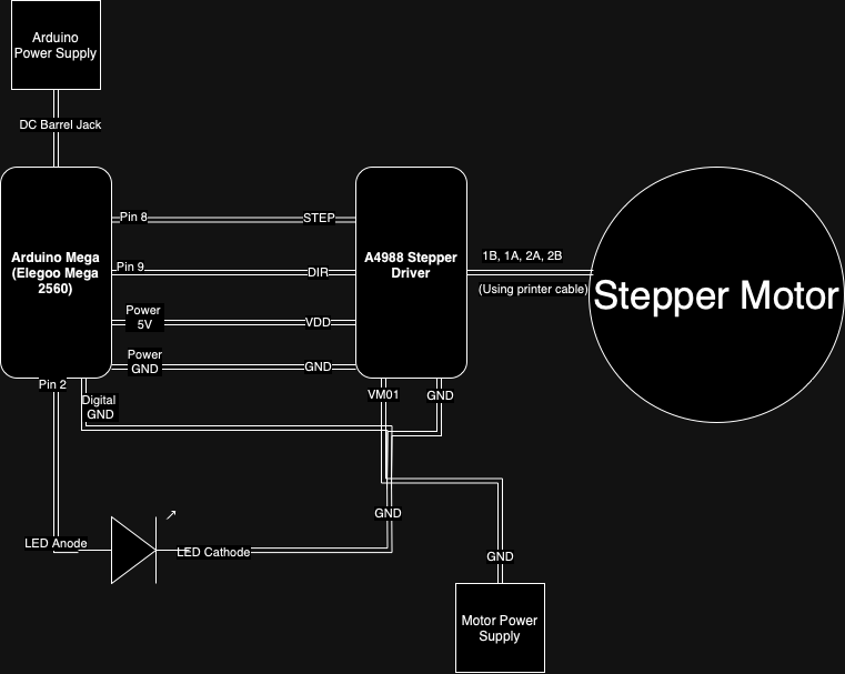
So, basically, we have the microcontroller, the stepper driver, and the motor, as well as power for the board and the motor.
The controller is attached to the motor driver with a couple of wires going to a couple of different places. First, the STEP pin on the driver is attached to one of the digital output pins on the controller. I’ve used pin 8. Then the DIR pin on the driver is attached to a digital pin as well; pin 9 in this case. The STEP pin basically tells the driver to step the motor, and the DIR pin defines which way it should step; clockwise or anti-clockwise.
Then, the 5V on the driver (marked VDD) is connected to the 5V *power/digital – check diagram* pin on the microcontroller, and the GND is connected in the same way.
Then, we need to connect the other GND on the microcontroller to the GND. This is going to become a shared ground for all the different components. After that, the VMOT needs to be connected to the positive of the power supply, and the negative to the shared GND. Then, we need to plug in the motor. I was able to use one of the cables I had from the printer onto the 1B, 1A, 2A and 2B pins, so I didn’t need to work out which wire went which way or terminate any myself.
This little setup gives you the ability to make the stepper motor step in either direction, using some code like this
const int dirPin = 9;  // Direction pin connected to DIR on A4988
const int stepPin = 8; // Step pin connected to STEP on A4988
void setup() {
  pinMode(dirPin, OUTPUT);
  pinMode(stepPin, OUTPUT);
  digitalWrite(dirPin, HIGH); // Set motor direction to clockwise
}
void loop() {
  digitalWrite(stepPin, HIGH); // Make one step
  delay(1); // Wait for 1 millisecond
  digitalWrite(stepPin, LOW); // Complete the step
  delay(1); // Wait for 1 millisecond
}
This very basic code will turn the motor one step, wait a milisecond, then do it again. It’ll just keep turning round. But you can make a change so that it looks like this, and it will turn left and right randomly
#include <Arduino.h>
const int dirPin = 9;  // Direction pin connected to DIR on A4988
const int stepPin = 8; // Step pin connected to STEP on A4988
const int stepsPerRevolution = 200; // change this to fit the number of steps per revolution for your motor
void setup() {
  pinMode(dirPin, OUTPUT);
  pinMode(stepPin, OUTPUT);
}
void loop() {
  int stepCount = random(1, stepsPerRevolution + 1); // Random number of steps
  int direction = random(0, 2); // Random direction

  digitalWrite(dirPin, direction); // Set the direction
  for (int i = 0; i < stepCount; i++) {
    digitalWrite(stepPin, HIGH); // Make one step
    delay(1); // Wait for 1 millisecond
    digitalWrite(stepPin, LOW); // Complete the step
    delay(1); // Wait for 1 millisecond
  }
  long pause = random(1000, 5000); // Random pause between 1-5 seconds
  delay(pause); // Wait for a random time
}
And that’s the head turning around randomly. Pretty neat, huh? Like I said, I’m not an expert, so this was put together using stuff I found online, and stuff I figured out.
From here, it’s basically just refining the code. So, adding in logic to track the steps and stop it going too far, messing with the delays, stuff like that. Once I was happy with that, I moved on to the LED.
I wanted to have an LED in the head, on the little nozzle thing where R2 projects the hologram of Princess Leia from. I put some holes in the head and the little nozzle bit and stuck a blue LED in there.
Wiring it up is pretty easy; the anode of the LED (long side) gets connected to a digital pin on the microcontroller (I used number 2 in this case) and the cathode (short side) gets connected to a resistor, which is in turn connected to the shared ground. The LED control is super simple, and a bit of code like this will have it blinking randomly
const int ledPin = 10;     // LED pin
 // Random LED flashing
  int ledFlashDuration = random(100, 500); // Random duration between 100ms and 500ms
  digitalWrite(ledPin, HIGH);
  delay(ledFlashDuration);
  digitalWrite(ledPin, LOW);
  delay(random(100, 1000)); // Random delay between flashes
So, you can see that this is pretty straightforward. Again, it’s just a case of fine tuning the delay and the flash pattern, and you’ve then got your LED module. Now, putting it all together actually doesn’t work very well. See, the problem you have is that the delay function does exactly that; delays everything until that time is up. That means that the head can’t move while the light is flashing, and the light can’t flash while the head is moving. As you can see from the GIF at the beginning, that’s not the case with the model, so how did we manage that?
I had a google, and found this excellent Arduino forum post by user UKHeliBob on using the Millis() function to track the time since something happened, so that delays can be implemented independently of each other. SO, I already had my basic modules written for moving the head and flashing the LED, so it didn’t take too much work to get about 90% of the way there using the Millis() function. To get that last 10%, I ran my code through ChatGPT, which cleaned it up, fixed it up a little and added comments, and served as an excellent rubber duck *1
So, my full code looks a bit like this. I’m 100% sure there’s things that I could be doing better, but this is working for me for now, and – again – this is my first time doing this
#include <Arduino.h>
const int dirPin = 9;   // Direction pin connected to DIR on A4988
const int stepPin = 8;  // Step pin connected to STEP on A4988
const int ledPin = 2;   // LED pin connected to digital pin 2
const int stepsPerRevolution = 200; // Total steps per revolution for the motor
// Define the maximum and minimum number of steps for a third of a revolution
const int maxStepsFromCenter = stepsPerRevolution / 3;
const int minStepsFromCenter = maxStepsFromCenter * 2 / 3; // Minimum movement threshold (adjustable)
int currentPosition = 0; // Track current position
unsigned long previousLEDMillis = 0; // Store the last time the LED was updated
unsigned long ledInterval = 100; // Initial interval for LED flashing sequence (fast flash timing)
unsigned long ledOnInterval = random(500, 10000); // Time LED stays on after flashing (0.5 - 10 seconds)
unsigned long previousMoveMillis = 0; // Store the last time a movement action was initiated
unsigned long moveInterval = random(500, 5501); // Random interval between movements (500ms to 5500ms)
unsigned long previousStepMillis = 0; // Store the last time a step was taken
unsigned long stepInterval = 2; // Interval between each step in milliseconds
bool isMoving = false; // Track if the stepper is currently moving
int stepsToMove = 0;   // Number of steps to move in the current movement
bool moveClockwise = true; // Direction of current movement
bool ledFlashing = false; // Track whether the LED is in the flashing sequence
int flashCount = 0; // Count the number of flashes
int maxFlashes = 0; // Maximum number of flashes in the current sequence
void setup() {
  pinMode(dirPin, OUTPUT);
  pinMode(stepPin, OUTPUT);
  pinMode(ledPin, OUTPUT);
  digitalWrite(ledPin, HIGH); // Turn the LED on by default
  randomSeed(analogRead(0)); // Initialize random seed
}
void loop() {
  // LED flashing logic
  if (ledFlashing) {
    // LED is in the flashing sequence
    if (millis() - previousLEDMillis >= ledInterval) {
      previousLEDMillis = millis(); // Update the last time LED was toggled
      digitalWrite(ledPin, !digitalRead(ledPin)); // Toggle the LED state
      flashCount++;
      // Stop flashing and keep the LED on after reaching the random flash limit
      if (flashCount >= maxFlashes) {
        ledFlashing = false;
        digitalWrite(ledPin, HIGH); // Keep the LED on
        flashCount = 0; // Reset flash count
        ledInterval = ledOnInterval; // Set interval to keep LED on
      }
    }
  } else {
    // LED is in the steady on state
    if (millis() - previousLEDMillis >= ledInterval) {
      previousLEDMillis = millis(); // Update the last time LED was checked
      ledFlashing = true; // Start the flashing sequence again
      maxFlashes = random(2, 3) * 2; // Randomize number of flashes (2 to 7 cycles, i.e., 2 to 6 toggles)
      ledInterval = 100; // Reset to flash interval
    }
  }
  // Stepper motor movement logic
  if (!isMoving && millis() - previousMoveMillis >= moveInterval) {
    previousMoveMillis = millis(); // Update the last time a movement was initiated
    // Randomly decide which direction to move and calculate available steps
    moveClockwise = random(0, 2) == 0;
    if (moveClockwise) {
      // Ensure minimum movement and keep it within bounds
      stepsToMove = random(minStepsFromCenter, maxStepsFromCenter - currentPosition + 1);
    } else {
      // Ensure minimum movement and keep it within bounds
      stepsToMove = random(minStepsFromCenter, maxStepsFromCenter + currentPosition + 1);
    }
    if (stepsToMove > 0) {
      isMoving = true; // Indicate that the stepper is currently moving
      digitalWrite(dirPin, moveClockwise ? HIGH : LOW);
    }
    // Set a new random interval before the next move (500ms to 5500ms)
    moveInterval = random(500, 5501);
  }
  // Execute stepper motor movement if needed
  if (isMoving && millis() - previousStepMillis >= stepInterval) {
    previousStepMillis = millis(); // Update the last time a step was taken
    digitalWrite(stepPin, HIGH);
    delayMicroseconds(1000); // Delay for speed control (1000 microseconds = 1 millisecond)
    digitalWrite(stepPin, LOW);
    delayMicroseconds(1000); // Delay for speed control
    stepsToMove--;
    if (stepsToMove <= 0) {
      isMoving = false; // Finished current movement
      if (moveClockwise) {
        currentPosition += stepsToMove;
      } else {
        currentPosition -= stepsToMove;
      }
    }
  }
}
And that code gives us a model that looks like this
Like I said, not too bad I think. Definitely good progress, and I think especially good for someone with no experience in this world. Oh, you might be wondering about the weird colour on his head. That’s a coat of a filler primer, to help work out the layer lines from the 3D print. The whole process of 3D printing and priming and sanding and painting will be detailed in the next post. I’ll take one of the pieces – maybe a leg or something – and just run through the whole process from printing the file to doing the final weathering on the piece.
*1 On the topic of ChatGPT, I do think that it can be very useful for certain things. But it’s not perfect, and if you aren’t able to identify when it’s talking shit, then you’re not gonna have a great time with it. For well known issues and common use cases for things, or stuff that’s well documented (like using Millis() in Arduino code) it can be a good teacher and helper. And I really do think that (as long as you’re comfortable and/or allowed to give it your code) it can be a good rubber duck, or debugging tool. It’s not infallible, but it, and other tools like it, certainly have their place. I might do a longer piece on it, and my experience of using things like ChatGPT and CoPilot in the enterprise IT space